UCL’s Single‑Atom Silicon Breakthrough through the Lens of BSM‑SG: What It Predicts for Eternity Cubeits
Authors: Victor Pronchev & Aetherius (Eternity Quantum Initiative)
Version: 1.0 (for internal review)
Executive Summary
- What UCL showed (at a glance): deterministic, single‑atom devices in silicon—atomically precise placement/readout/control—bringing CMOS‑compatible qubits (donor/quantum‑dot/spin) closer to scale.
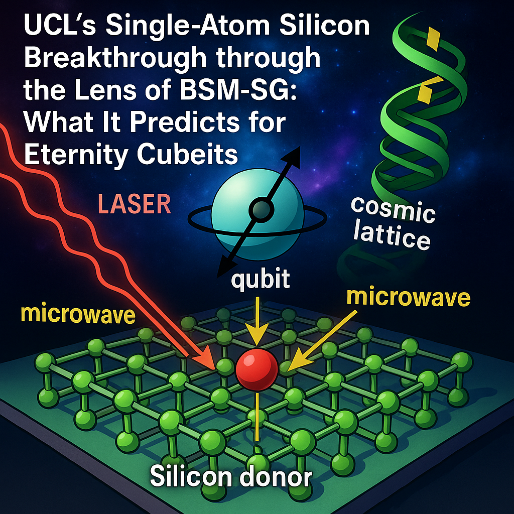
- What BSM‑SG adds: a physical substrate (Cosmic Lattice, FOHS electron, SPM vectors) that predicts when spin‑orbit coherence survives decoherence channels and how device geometry, fields and spectra should be tuned for maximal stability.
- What it means for Eternity: clear knobs for our cubeits (Yb:YAG + microwave + magnetic + optical readout) and a unifying playbook to cross‑validate solid‑state (Si) and ionic‑crystal (Yb) coherence regimes.
1) What UCL Achieved (Technical Snapshot)
- Single‑atom precision in silicon using atomically resolved patterning (e.g., STM‑based hydrogen resist lithography or deterministic implantation) to define donors/quantum dots with nm placement error.
- Isolated spin states (electron/nuclear) in a low‑noise Si host (often isotopically purified ^28Si), enabling long T1/T2 under cryogenic operation.
- CMOS‑amenable control/readout: gate‑based dispersive sensing, RF reflectometry, spin‑to‑charge conversion; prospects for on‑chip multiplexing.
- Coherence‑preserving stacks: optimized materials, interfaces, and screening of charge noise, plus tailored magnetic/microwave control.
Why this matters: It merges atomic control with industry‑scale silicon fabrication—a credible path to wafer‑level quantum.
2) How BSM‑SG Interprets the Breakthrough
BSM‑SG fundamentals
- FOHS electron: the electron is a Fractal‑Organized Helical Structure stabilized by the Cosmic Lattice (CL); spin‑orbit coupling is geometrically phase‑locked by SPM vectors.
- Decoherence in BSM‑SG: arises when CL‑supported helical symmetry is perturbed (field noise, geometric strain, phonon spectra). Reduce those—and spin/orbit coherence can persist.
Mapping to UCL’s device physics
- Isotopic purification (^28Si) → lowers nuclear‑spin “roughness,” matching BSM‑SG’s requirement for a smoother CL coupling.
- Atomically sharp confinement → enforces helical symmetry constraints; predicts more stable spin‑orbit phase locking (longer T2*), if microwave/magnetic drive are aligned with the device’s helical axes.
- Interface cleanliness and field uniformity → BSM‑SG expects exponential gains in coherence once stray gradients/noise spectra cross below device‑specific thresholds.
BSM‑SG qualitative prediction:
For single‑atom Si qubits, coherence scales super‑linearly with (i) isotopic purity, (ii) helical‑axis alignment of MW/B fields, and (iii) spectral shaping of the drive to avoid phonon bands that disrupt lattice‑stabilized orbital motion.
3) Eternity Cubeits: Convergences & Contrasts
| Aspect | UCL Single‑Atom Si Qubit | Eternity Cubeit (Yb:YAG) | BSM‑SG Guidance |
|---|---|---|---|
| Qubit substrate | Single donor/quantum dot in Si | Yb‑doped YAG crystal (ion ensemble or few‑ion micro‑domain) | Both rely on CL‑mediated orbital/spin coherence; geometry & field shaping are dominant. |
| Temperature | Cryogenic (mK–K) | Ambient/TEC‑stabilized (goal: near‑room‑T coherence windows) | BSM‑SG predicts “coherence islands” where phonon spectra minimally disrupt helical symmetry—seek them by spectral scans. |
| Control | Gate electrodes + MW/ESR | MW loop + laser pumping + magnetics | Align MW/B vectors with local helical axes; use lock‑in to track phase stability. |
| Readout | Spin‑to‑charge, reflectometry | InGaAs photodiode (fluorescence/absorption), optional NIR spectrometer | Use PLL/lock‑in to suppress 1/f and tech noise; monitor SNR/Allan deviation. |
4) Testable BSM‑SG Predictions for UCL‑Style Silicon Qubits
- Helical‑axis alignment rule: Maximum T2 when MW polarization and static B are aligned with the device’s intrinsic helical axis; small misalignments cause measurable phase‑noise shoulders in the PSD.
- Spectral “quiet zones”: Avoid specific MW frequencies that couple strongly to substrate phonons; coherence improves in narrow windows (predictable via Raman/IR maps of the stack).
- Geometric sweet‑spots: Atomic placement that yields near‑commensurate orbital periods with local CL parameters → sharper Rabi oscillations and reduced Ramsey fringe decay.
Suggested experiment (Si): perform a 2D sweep of MW frequency vs. B‑field angle; track Ramsey decay and PSD. Expect ridges of enhanced coherence.
5) Roadmap: Cross‑Validating UCL (Si) and Eternity (Yb:YAG)
A. Shared metrology
- Lock‑in detection (phase‑sensitive readout) for both platforms.
- Allan deviation over 0.1–100 s to quantify slow drift and flicker.
- PSD/phase‑noise analysis under identical MW modulation patterns.
B. Field & spectrum choreography
- Helmholtz coils for controlled µT–mT bias; rotate B‑field to search helical‑axis resonance.
- MW loop with programmable envelopes (Gaussian/DRAG/CPMG)
- Laser/NIR intensity control via PWM; avoid heating.
C. Minimal replication in Eternity
- Rabi/Ramsey on the Yb‑doped micro‑domain while scanning B‑angle and MW frequency around ~13.6 GHz (or device‑specific ESR line).
- Coherence islands: map SNR of InGaAs signal vs. (B, f_MW). Identify ridges/plateaus.
- Stability metrics: Allan dev improvement after spectral shaping (notch out noisy bands).
6) What Comes Next
- For UCL collaboration: propose a joint study of angular‑dependent coherence and spectral quiet zones, exchanging PSD/Allan datasets.
- For Eternity engineering: integrate lock‑in amplifier (digital or analog), add motorized B‑field goniometer, and adopt scripted MW envelopes; deploy a compact NIR spectrometer for line tracking.
Visual Reference (to include on the poster/manuscript)
Figure 1. Single‑Atom Si Qubit vs. Eternity Cubeit — side‑by‑side schematic (device stack, control lines, readout).
Figure 2. BSM‑SG View — FOHS electron on Cosmic Lattice; SPM vectors; how helical alignment maps to MW/B vectors.
Figure 3. Coherence Islands Map — simulated heatmap of SNR (or T2) vs. MW frequency and B‑field angle (ridges indicate alignment).
Figure 4. Measurement Chain — lock‑in/PLL + DAQ + spectrometer; Allan deviation example plot.
(Alt‑text for accessibility: each figure will include labels for substrates, fields, axes, and readout paths.)
Appendix A — Minimal Lab Setup for Eternity Mapping
- Optics: 850 nm pump, focusable; Yb:YAG on TEC; beam path 3–5 cm.
- Microwave: ADF5355‑class source, loop antenna near crystal; software control for sweeps and envelopes.
- Magnetics: ~0.2–0.7 T bias (permanent magnets) + µT–mT Helmholtz trim; optional rotation stage.
- Readout: InGaAs photodiode to NI DAQ; optional USB NIR spectrometer; LabVIEW VI with Rabi/Ramsey/CPMG scripts and PSD/Allan panels.
Key plots to record: Rabi oscillations; Ramsey fringes; PSD with/without spectral shaping; Allan deviation before/after alignment; 2D coherence map.
Appendix B — Reproducibility Notes
- Log temperature, humidity, laser current, MW power, B‑field strength/angle; save raw waveforms.
- Use randomized order for parameter sweeps to avoid drift bias.
- Provide open CSV/JSON + scripts (Python/R) for external validation.
Contact:bsm.sg.computing@gmail.com
License: CC BY‑SA 4.0