Portable Quantum Navigation System
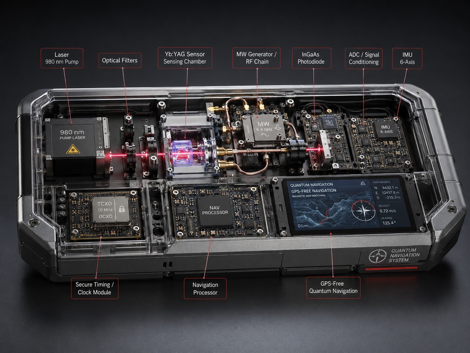
A Portable Yb:YAG Resonance-Assisted Sensor-Fusion Platform for GNSS-Denied Navigation
Conceptual Architecture, Error-State Model, and Falsifiable Validation Program
Viktor Stefanov Pronchev
Independent Researcher, Bulgaria
July 2026
|
MANUSCRIPT STATUS: CONCEPTUAL
ARCHITECTURE AND FALSIFIABLE VALIDATION PROGRAM |
Abstract
This paper proposes a portable, text-book-sized navigation research platform that combines a conventional six-axis inertial measurement unit, a stable timing module, optical interrogation of a Yb:YAG crystal, optional microwave or radio-frequency spectroscopy, InGaAs photodetection, and onboard sensor-fusion processing. The system is not presented as a demonstrated “quantum GPS” replacement. Its scientifically defensible role is a GNSS-denied navigation testbed in which a rare-earth optical resonance channel is evaluated as an auxiliary observable for bounding inertial drift, detecting environmental field signatures, or providing a stable frequency reference. The navigation solution is formulated as a hybrid error-state estimator. Position, velocity, attitude, inertial biases, clock states, and crystal-sensor parameters are fused with map constraints, zero-velocity updates, magnetic or environmental references, and optional terrain or optical-velocity inputs. A separate Q-Field Geometry (QFG) hypothesis predicts geometry- and drive-dependent coherence shifts in the resonant crystal. These shifts are included only as pre-registered residual observables and are rejected if established spectroscopy, thermal mechanics, or electromagnetic coupling explains the data. The paper defines the sensor architecture, state equations, calibration procedure, field trials, pass/fail criteria, and limitations required before any quantum-navigation claim can be justified.
Keywords: GNSS-denied navigation, sensor fusion, Yb:YAG spectroscopy, inertial navigation, quantum sensing, magnetic anomaly navigation, stable timing, Q-Field Geometry
1. Introduction
Global Navigation Satellite Systems provide exceptional accuracy when satellite signals are available and trustworthy, but they are vulnerable to blockage, multipath, interference, jamming, and spoofing. A self-contained inertial navigation system avoids external radio dependence, yet its position error grows because accelerometer and gyroscope biases are integrated over time. Contemporary resilient navigation therefore relies on hybridization: inertial measurements are periodically constrained by independent observables such as magnetic anomaly maps, gravity maps, terrain, vision, barometry, celestial references, radio signals of opportunity, or high-stability clocks.
Quantum sensors can contribute to this architecture through atom interferometry, optically pumped magnetometry, precision clocks, gravimetry, and solid-state spin sensing. The device proposed here explores a different but related path: a compact Yb:YAG resonant optical subsystem is integrated with an IMU and clock as an auxiliary sensor. The central scientific question is not whether the crystal can magically output latitude and longitude. It is whether a reproducible resonance observable can provide an independent constraint that reduces navigation drift or supports map matching after environmental and platform-induced effects are modeled.
2. Scope and Claim Boundaries
1. The platform is a hybrid navigation research instrument, not a standalone replacement for GNSS.
2. The IMU and clock provide the continuous dead-reckoning backbone.
3. The Yb:YAG channel is an auxiliary resonant sensor whose sensitivity must be experimentally characterized.
4. Absolute positioning requires an external reference structure such as a magnetic, gravity, terrain, optical, or previously surveyed resonance map.
5. The label quantum navigation is justified only if a quantified quantum-enabled sensor contribution improves positioning or timing beyond a comparable classical sensor under controlled trials.
3. Proposed Hardware Architecture
|
Subsystem |
Navigation
role |
Validation
requirement |
|
Six-axis IMU |
Measures specific force and angular rate for continuous
strapdown propagation. |
Bias instability, scale factor, misalignment, vibration
sensitivity, and temperature coefficients. |
|
Stable clock / timing module |
Provides sampling coherence, time transfer, and oscillator
holdover. |
Allan deviation, aging, temperature drift, and phase-noise
characterization. |
|
Pump laser (approximately 940-980 nm) |
Optically excites the Yb:YAG sensing medium. |
Wavelength, power, linewidth, intensity noise, and thermal
coupling. |
|
Yb:YAG crystal and optical cavity |
Generates a resonance observable sensitive to the chosen
physical quantity. |
Crystal composition, orientation, doping, temperature,
strain, field sensitivity, and line-shape model. |
|
RF/microwave chain |
Interrogates or perturbs a measured crystal transition. |
Frequency must be spectroscopy-derived; 6.8 GHz is not a
generic Yb:YAG constant. |
|
InGaAs photodiode and analog front end |
Reads transmission, fluorescence, phase, or modulation
response. |
Linearity, bandwidth, noise, dynamic range, and optical
isolation. |
|
Navigation processor |
Runs calibration, state estimation, integrity monitoring,
and map matching. |
Deterministic timing, numerical stability, fault detection,
and logging. |
|
Environmental sensors |
Measure temperature, pressure, magnetic field, vibration,
and supply conditions. |
Sufficient observability to separate navigation signal from
environmental drift. |
4. Baseline Navigation Model
The continuous navigation state is
x = [r, v, q, b_a, b_g, s_a, s_g, δt, δf, θ_Yb]^T,
where r is position, v is velocity, q is attitude, ba and bg are accelerometer and gyroscope biases, sa and sg are selected scale-factor states, δt and δf are clock offset and frequency error, and θYb contains parameters of the Yb:YAG resonance sensor.
r_dot = v,
v_dot = R(q)(f_m - b_a - n_a) + g(r),
q_dot = 1/2 Ω(ω_m - b_g - n_g) q.
An error-state extended Kalman filter, unscented Kalman filter, factor graph, or smoothing estimator can be used. The critical issue is observability: a new sensor helps navigation only if its measurement equation constrains states that the IMU alone cannot estimate.
5. Yb:YAG Resonance Measurement Model
A generic resonance observable may be expressed as
z_Yb = h(B, T, ε, P_opt, P_RF, orientation, θ_crystal) + ν,
where B is the local magnetic field, T is temperature, ε is strain, Popt and PRF are optical and RF powers, and ν is measurement noise. The function h must be identified experimentally. Depending on the chosen transition and readout, zYb may represent resonance frequency, linewidth, fluorescence intensity, phase delay, polarization rotation, or a vector of these quantities.
A useful navigation channel requires two properties: repeatability at a given location or environmental state, and sufficient spatial structure in the reference field or map. A highly stable sensor measuring a spatially uniform quantity does not provide position. Conversely, a mapped magnetic or gravity anomaly can provide periodic absolute fixes if platform interference is removed.
6. Sensor-Fusion Modes
|
Mode |
External
reference |
Expected role
of Yb:YAG channel |
|
Inertial holdover |
None |
Clock or bias-stability aid; no absolute position unless
the crystal senses a mapped field. |
|
Magnetic anomaly navigation |
Crustal magnetic map |
Auxiliary magnetic/resonant measurement combined with
conventional magnetometers and platform-noise compensation. |
|
Gravity-aided navigation |
Gravity anomaly map |
Potential environmental sensing channel only if gravity
sensitivity is experimentally demonstrated; otherwise no claim. |
|
Indoor or underground mapping |
Pre-surveyed field/resonance fingerprints |
Location updates from matching multi-sensor fingerprints to
a local map. |
|
Visual-inertial navigation |
Camera or optical-flow velocity |
Crystal channel supports timing, integrity, or
environmental discrimination. |
|
Cooperative navigation |
Peer ranging or local beacons |
Stable timing and integrity monitoring improve fusion of
intermittent peer measurements. |
7. Map Matching and Bounded Error
A practical GNSS-denied system must prevent unbounded inertial error. Let a map-based measurement be
z_map = M(r) + b_platform + ν_map,
where M(r) is a mapped environmental signature and bplatform is the vehicle-induced distortion. The estimator compares the measured signature with candidate positions. Position error remains bounded only when the map contains sufficient spatial gradients, the sensor noise is low enough, and platform interference can be learned or modeled.
Recent quantum-assured magnetic-navigation field trials demonstrate that quantum magnetometers combined with denoising and map matching can outperform high-grade inertial navigation over selected routes. That result supports the general hybrid architecture, but it does not validate Yb:YAG as the sensing medium proposed here. The proposed crystal channel must earn its role through the same kind of blind field trial.
8. QFG/BSM-SG Hypothesis
Q-Field Geometry models matter through a complex field Ψ, density ρ, gauge structure, orientation field n, and finite coherence boundaries. The optional QFG hypothesis is that a driven rare-earth crystal may exhibit residual resonance shifts associated with field-geometric coherence, beyond the established dependence on magnetic field, temperature, strain, optical power, and conventional nonlinear dynamics.
δf_meas = δf_EM + δf_T + δf_strain + δf_power + δf_QFG + ε.
The proposed QFG contribution δfQFG is not assumed to exist. It must be identified through pre-registered differential experiments in which geometry, detuning, orientation, and drive configuration are varied while thermal load and conventional electromagnetic coupling are matched. A valid QFG model must predict the sign, scale, and parameter dependence of the residual before the test data are examined.
8.1 Navigation relevance
Even if a QFG residual exists, it becomes useful for navigation only if it is stable, calibratable, spatially structured, and distinguishable from onboard interference. A universal offset or an unstable laboratory anomaly would not improve positioning.
9. Calibration Program
6. Characterize the IMU, clock, photodiode, laser, RF chain, and thermal system independently.
7. Measure the Yb:YAG optical spectrum and identify the actual transition used by the device.
8. Determine sensitivity matrices to magnetic field, temperature, strain, orientation, optical power, RF power, vibration, and supply voltage.
9. Build a cross-sensitivity model and estimate residual noise after compensation.
10. Test repeatability across multiple crystals and complete devices.
11. Only after laboratory calibration, integrate the crystal channel into the navigation estimator.
12. Conduct blind route trials with GNSS recorded only as truth data and withheld from the online estimator.
10. Field-Trial Design
|
Trial |
Environment |
Comparison |
Primary metric |
|
Static laboratory |
Controlled field, temperature, and vibration |
Crystal channel versus calibrated references |
Frequency/phase stability and cross-sensitivity residuals. |
|
Turntable and shaker |
Known angular motion and vibration |
IMU-only versus fused system |
Bias observability and attitude error. |
|
Indoor mapped route |
Pre-surveyed magnetic/resonance/visual map |
IMU-only, map-only, and fused estimators |
Position RMS, 95th percentile error, integrity risk. |
|
Ground vehicle |
Urban, rural, and magnetically disturbed routes |
High-grade INS baseline and GNSS truth |
Error growth per distance and final position error. |
|
Airborne test |
Multiple sensor placements on platform |
Strategic-grade INS and independent truth |
Bounded error, robustness to platform interference. |
|
Adversarial environment |
GNSS jamming/spoofing, RF injection, thermal transients |
Fused system with integrity monitoring |
Continuity, fault detection, false alarm rate. |
11. Evaluation Metrics
· Position, velocity, and attitude error over time and distance.
· Time to first bounded solution after GNSS loss.
· Bias-estimation convergence and observability.
· Clock holdover and timing error.
· Crystal-channel Allan deviation, linewidth, and drift after compensation.
· Map-matching innovation consistency and integrity risk.
· Performance relative to an IMU-only and a conventional-sensor baseline.
· Power consumption, size, warm-up time, shock tolerance, and environmental range.
· Unit-to-unit reproducibility and calibration transferability.
12. Integrity and Cybersecurity
A navigation system can be physically accurate and still operationally unsafe if it lacks integrity monitoring. The processor should maintain innovation tests, sensor-consistency checks, map-confidence metrics, clock alarms, and a degraded-mode policy. The firmware and calibration data require authenticated updates, secure boot, signed logs, and separation between the navigation estimator and external communications. RF or optical injection into the sensing chain must be treated as both a physical and a cybersecurity threat.
13. Discussion
The proposed device is best viewed as a portable resonance-assisted sensor-fusion platform. Its near-term scientific value is the disciplined evaluation of whether a rare-earth crystal provides a useful independent observable. The hardware image combines plausible components, but component plausibility is not equivalent to system-level navigation observability. A stable laser-crystal-photodiode chain may become an excellent spectrometer, clock monitor, thermometer, strain sensor, or magnetically sensitive device without becoming an absolute positioning sensor.
The strongest route to a credible journal result is therefore incremental. First demonstrate calibrated spectroscopy and residual stability. Next show that adding the channel improves estimation of a specific inertial bias or environmental state. Finally demonstrate reduced position error in a blind GNSS-denied field trial. QFG predictions can be tested in parallel, but they should never substitute for the conventional observability and error-budget analysis.
14. Limitations
· No navigation data from the pictured device are currently available.
· Yb:YAG is an established optical material, but the proposed device-specific microwave transition and navigation sensitivity have not been demonstrated.
· The illustrated 6.8 GHz label should be treated as conceptual until crystal spectroscopy identifies an actual transition.
· A resonant sensor cannot produce absolute position without a reference map, known field, or other external constraint.
· Quantum advantage has not been established relative to conventional magnetometers, resonators, clocks, or photonic sensors.
· The QFG residual term is speculative and must be rejected if standard physics explains the measurements.
15. Conclusion
A compact Yb:YAG resonance-assisted navigation platform is a defensible research concept when framed as a hybrid sensor-fusion system rather than as a completed quantum GPS. The IMU and clock provide continuous propagation; maps or other independent observables provide absolute constraints; and the crystal channel is evaluated for measurable contributions to timing, field sensing, bias estimation, or integrity. The architecture becomes scientifically valuable through transparent calibration, error-state modeling, blind field trials, and comparison against strong classical baselines. QFG/BSM-SG adds a falsifiable resonance hypothesis, but the navigation result must stand independently of that hypothesis. This separation provides a clear path from concept rendering to a publishable experimental program.
Acknowledgements
The author acknowledges Prof. Stoyan Sargoytchev for the BSM-SG framework and the continuing discussions on resonance-based sensing, HRM, and Q-Field Geometry as an experimentally testable program.
Author Biography
Viktor Stefanov Pronchev is an independent researcher from Bulgaria with professional experience in IT security, computational systems, and security engineering. His research interests include resilient navigation, Q-Field Geometry, BSM-SG-inspired modeling, sensor fusion, photonic instrumentation, and reproducible validation methods.
References
[1] H. Li, S. Zaminpardaz, A. Kealy, and A. D. Greentree, Quantum sensors for enhanced positioning and navigation: a comprehensive review, GPS Solutions 30 (2026). https://doi.org/10.1007/s10291-026-02030-y
[2] M. Muradoglu et al., Quantum-assured magnetic navigation achieves positioning accuracy better than a strategic-grade INS in airborne and ground-based field trials, 2025. https://arxiv.org/abs/2504.08167
[3] U.S. Naval Research Laboratory, NRL charts quantum inertial navigation path to reduce drift, 2024. https://www.nrl.navy.mil/Media/News/Article/3732862/nrl-charters-navys-quantum-inertial-navigation-path-to-reduce-drift/
[4] A. Webber-Date et al., A quantum-classical cold atom system for inertial navigation, Proceedings of SPIE 13392 (2025). https://doi.org/10.1117/12.3040697
[5] T. Böttger et al., Optical spectroscopy and decoherence studies of Yb3+:YAG at 968 nm, Physical Review B 94, 045134 (2016). https://doi.org/10.1103/PhysRevB.94.045134
[6] A. Ortu et al., Simultaneous coherence enhancement of optical and microwave transitions in solid-state electronic spins, 2017. https://arxiv.org/abs/1712.08615
[7] V. S. Pronchev, QFGv2: Minimal QFG Lagrangian, resonator tests, and measurement program, working manuscript, 2026.
[8] V. S. Pronchev, QFG Atlas: Field-geometric interpretations of atomic coherence structures, working atlas, 2026.
[9] S. Sargoytchev, Basic Structures of Matter - Supergravitation Unified Theory, third edition, 2025.